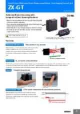
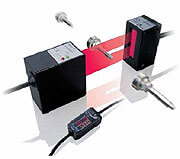
ZX-GT
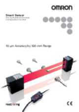
Micrometru cu laser inteligent - Precis şi rapid pe toate suprafeţele
Noul micrometru cu laser inteligent ZX-GT completează platforma Omron de măsurare cu laser inteligent. ZX-GT poate detecta marginile, poate măsura diametrele obiectelor şi poate calcula cu precizie poziţia tuturor tipurilor de materiale. Pe baza tehnologiei CCD, ZX-GT realizează precizie şi viteză ridicate în condiţii dificile de mediu. Obiectele transparente, suprafeţele reflectorizante sau diferite poziţii nu au influenţă asupra rezultatelor. Software-ul PC Smart Monitor ajută la instalarea şi configurarea cu uşurinţă a micrometrului laser.
- Precizie ridicată: 5 – 10 µm
- Pentru toate suprafeţele
- Distanţă mare de detectare: < 500 mm
- Lăţime linie măsură de până la 28 mm
- Unitate de calcul pentru mai multe capete de măsură
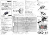
Specificaţii şi informaţii pentru comenzi
Ordering information
Sensors
Controller
Accessories (order separately)
Set of interface unit and setup software PCs
Interface unit(RS-232C/binary output)
Setup software PCs
Calculating units
Receiver-controller extension cable
Specifications
Sensor
|
Visible semiconductor laser diode (wavelength 650 nm, CLASS 1 of EN60825-1/IEC60825-1, CLASS of FDA(21CFR 1040.10 and 1040.11) |
||||
|
0.5 mm dia.1 |
0.5 mm dia.1 |
|||
|
±0.1% F.S.2 |
||||
|
10 µm (number of process values to average: 16)3 |
||||
|
±0.01% F.S/C4 |
||||
|
ON: Short-circuited with 0 V or 1.5 V max. |
ON: Short-circuited with power supply voltage or |
|||
|
NPN open-collector output |
PNP open-collector output |
|||
|
1,000 lx (incandescent light)5 |
||||
|
Operating: 0 to 40°C, storage: -15 to 50°C (with no icing or condensation) |
||||
|
10 to 150 Hz single-amplitude: 0.75 mm for 80 min each in X, Y and Z directions |
||||
Controller
|
Measurement cycle6 |
1.5 ms (standard mode (NORM)) |
||
|
Analog output8 |
For current output: 4 to 20 mA/F.S., max. load resistance 300
Ω
|
||
|
Timing input, bank switching input, zero reset input, reset input |
ON: short-circuited with 0 V or 1.5 V max. |
ON: short-circuited with power supply voltage or |
|
|
NPN open-collector output |
PNP open-collector output |
||
|
Judgment output indicator: HIGH (orange), PASS (green), LOW (orange) |
|||
|
Interrupted beam width measurement, incident beam width measurement, outer diameter measurement, center position measurement, IC lead pitch, |
|||
|
Measured value, resolution, threshold, voltage output value, current output value (number of display digits can be changed) |
|||
|
Sample hold, peak hold, bottom hold, peak-to-peak hold, average hold, delay hold |
|||
|
Optical axis adjust mode/light intensityt writing mode, variable binary level, variable edge filter, analog output scaling |
|||
|
2 possible on up to two controllers (calculation Unit ZX-CAL2 is required for connecting controllers to each other.) A-B, A+B, width |
|||
|
Measurement cycle setting, threshold setting, hysteresis setting, initialization, key lock |
|||
|
Operating: 0 to 50°C, storage: -15 to 60°C (with no icing or condensation) |
|||
|
10 to 150 Hz single-amplitude: 0.35 mm for 80 min each in X, Y and Z directions |
|||
|
Case: PBT (polybutylene terephthalate), cover: Polycarbonate |
|||
Interface unit
1. Distance between emitter and receiver: 500 mm, measurement object at 250 mm from receiver. Glass ends of chamfer 0.1 mm or more can be detected in glass edge measurement mode. (at binary level 70%)
2. Linearity is given to be a typical error with respect to an ideal straight line when the distance between the emitter and receiver is 100 mm and light is blocked at a distance of 50 mm from the receiver. (On the ZX-GT2840_, the measurement object is measured at a distance of 20 mm from the receiver.)
3. The amount of fluctuation (±3 σ ) in the analog output when the distance between the emitter and receiver is 100 mm and a ZX-GTC_ is connected
4.
Change in the light cutoff value on one side when the distance between the emitter and receiver is 100 mm and the light is half-cutoff at a distance of 50 mm from the receiver (On the
ZX-GT2840_, the measurement object is measured at a distance of 20 mm from the receiver.)
6. The first response time is “measurement cycle x (number of samples to average setting + 1) + 1 ms” max. For the second response time onwards, the specified measurement cycle time is output.
7. The response time in the high-speed mode (FAST) for the IC lead pitch and IC lead width judgment modes is 1 ms.
11.
Normally, wire the sync output wire directly to the emitter's sync input wire and run the controller in the standard mode. On an NPN type controller, use an NPN type emitter, and on a PNP type controller, use a PNP type emitter. Wiring of the sync wires is not required when the controller is run in the high-speed mode.
(Note, however, that the controller becomes more susceptible to the influence of ambient light in this case.)
Aveţi nevoie de asistenţă?
Suntem aici pentru a vă ajuta! Contactaţi-ne, iar specialiştii noştri vă vor ajuta să găsiţi cea mai bună soluţie pentru afacerea dvs.
Contactați-mă ZX-GT
Vă mulțumim pentru solicitarea trimisă. Vom reveni cu un răspuns cât mai curând posibil.
Întâmpinăm dificultăţi tehnice. . Formularul dumneavoastră nu a fost preluat cu succes. Vă rugăm să acceptaţi scuzele noastre şi să încercaţi încă odată mai târziu. Detalii: [details]
DownloadOfertă pentru ZX-GT
Prin completarea acestui formular puteţi face o cerere de ofertă. Vã rugãm completaţi toate câmpurile marcate cu *. Datele dumneavoastrã personale vor fi tratate cu confidențialitate.
Vă mulțumim pentru cererea de ofertă trimisă. Vă vom oferi informațiile cerute în cel mai scurt timp posibil.
Întâmpinăm dificultăţi tehnice. . Formularul dumneavoastră nu a fost preluat cu succes. Vă rugăm să acceptaţi scuzele noastre şi să încercaţi încă odată mai târziu. Detalii: [details]
DownloadDocumentare
_41(a)_instruction_sheet_en.jpg)