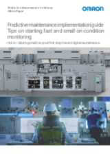
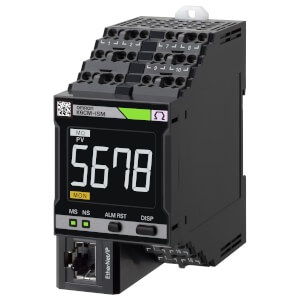
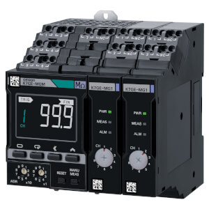
K6CM-CI2M
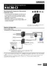
Dispozitiv de monitorizare a stării motorului – monitorizarea curentului
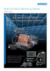
K6CM-CI2M este un partener de încredere care permite planificarea în avans a intervenţiilor de întreţinere la motoarele trifazate, evitându-se timpii morţi costisitori şi pierderea producţiei.
Controlerul K6CM-CI2M monitorizează forma de undă şi spectrul curente, indicatori foarte eficienţi ai stării întregii transmisii a motorului, recomandând intervenţii de întreţinere ori de câte ori se detectează abateri de la funcţionarea normală, înainte de apariţia unor probleme grave.
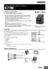
Monitorizarea stării pe bază de curent permite:
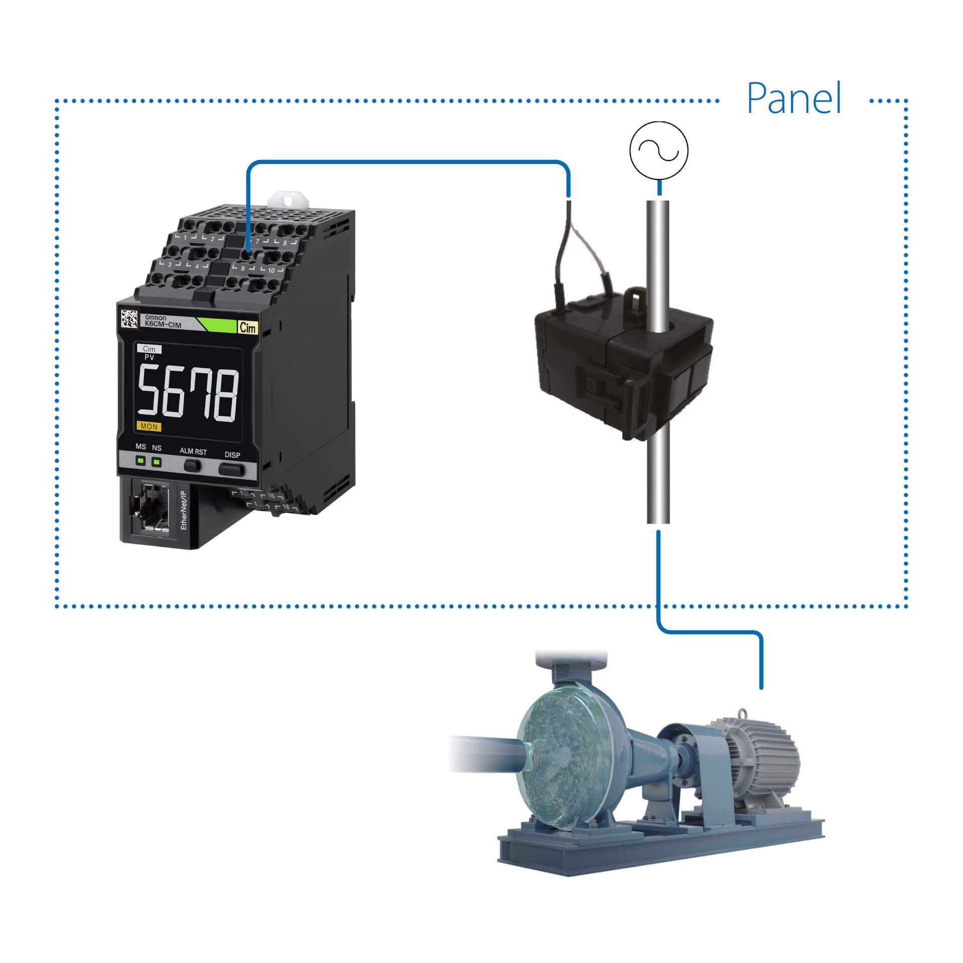
- Instalarea controlerului şi a traductorului de curent în panou, fără a fi nevoie de cablarea senzorilor la motor. K6CM-CI2M este cea mai bună soluţie pentru motoare şi pompe care sunt fie imersate, fie situate în incinte curate, în sisteme HVAC, în utilaje existente sau în locuri inaccesibile.
- Monitorizarea completă a stării întregii transmisii. S-a demonstrat că anomalii precum cavitaţia pompei, dezechilibrul sarcinii, curelele dezaliniate, problemele la stator şi rotor provoacă de fapt anomalii în forma de undă a curentului absorbit şi pot fi detectate uşor prin această metodă, chiar înainte de a se detecta modificări ale vibraţiilor.
- Configurarea sistemului în câteva minute, prin intermediul unui software uşor de utilizat, deoarece setarea parametrilor este foarte simplă şi algoritmul de analiză este integrat în controler.
- notificări în caz de avertisment/alarmă,
- monitorizare de la distanţă
- interacţiuni cu aplicaţii personalizate şi cu serverul MQTT.
Specificaţii şi informaţii pentru comenzi
| Produs | Supply voltage AC | Supply voltage DC | Descriere | |
|---|---|---|---|---|
|
|
100-240 V | Motor Condition Monitoring, AC, 3-phase, Induction motor, Current Analysis model, 100 to 240 VAC, Transistor control output, Push-in Plus, LCD display, Ethernet IP/Modus, applicable in environment with inverters |
|
|
|
|
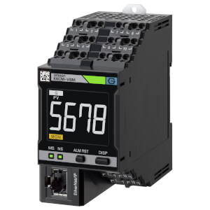
20.4-26.4 V | 20.4-26.4 V | Motor Condition Monitoring, AC, 3-phase, Induction motor, Current Analysis model, 24 VAC/VDC, Transistor control output, Push-in Plus, LCD display, Ethernet IP/Modbus, applicable in environment with inverters |
|
Aveţi nevoie de asistenţă?
Suntem aici pentru a vă ajuta! Contactaţi-ne, iar specialiştii noştri vă vor ajuta să găsiţi cea mai bună soluţie pentru afacerea dvs.
Contactați-mă K6CM-CI2M
Vă mulțumim pentru solicitarea trimisă. Vom reveni cu un răspuns cât mai curând posibil.
Întâmpinăm dificultăţi tehnice. . Formularul dumneavoastră nu a fost preluat cu succes. Vă rugăm să acceptaţi scuzele noastre şi să încercaţi încă odată mai târziu. Detalii: [details]
DownloadOfertă pentru K6CM-CI2M
Prin completarea acestui formular puteţi face o cerere de ofertă. Vã rugãm completaţi toate câmpurile marcate cu *. Datele dumneavoastrã personale vor fi tratate cu confidențialitate.
Vă mulțumim pentru cererea de ofertă trimisă. Vă vom oferi informațiile cerute în cel mai scurt timp posibil.
Întâmpinăm dificultăţi tehnice. . Formularul dumneavoastră nu a fost preluat cu succes. Vă rugăm să acceptaţi scuzele noastre şi să încercaţi încă odată mai târziu. Detalii: [details]
DownloadFeature
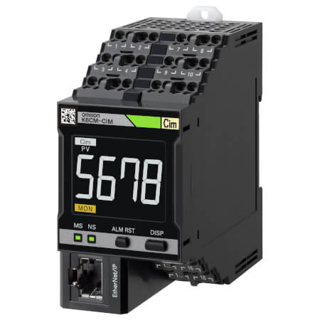
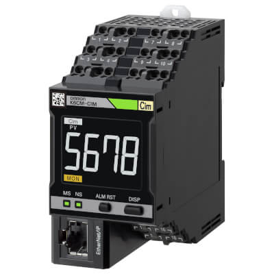
K6CM-CI2M poate fi instalat uşor în utilajele existente, deoarece nu este necesară cablarea motorului/pompei.
Controlerul şi traductorul de curent sunt amplasate în panou.
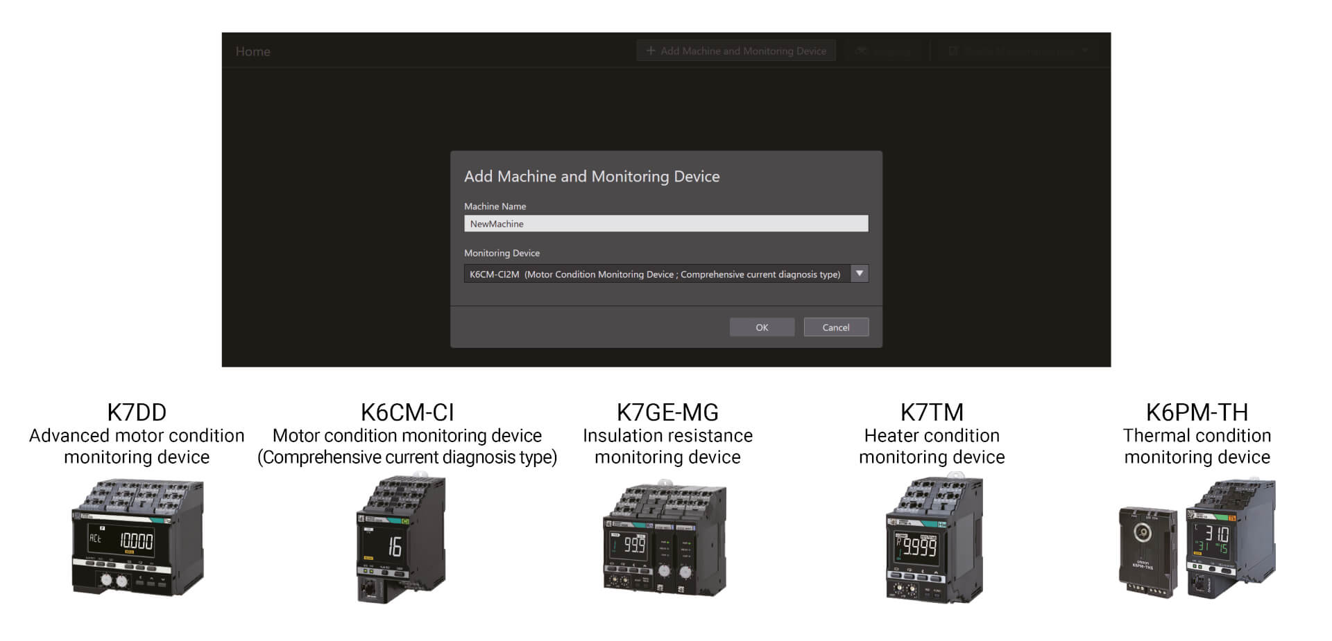
Dispozitivele de monitorizare a condiției pot fi configurate cu un singur instrument
Configurarea ușoară în trei pași din Unealta de configurare pentru monitorizarea condiției permite configurarea în loturi a unor game largi de dispozitive de monitorizare, cum ar fi a celor care monitorizează motoare, izolații și radiatoare. Poate fi folosită fără abilități speciale, ceea ce reduce eforul de instruire
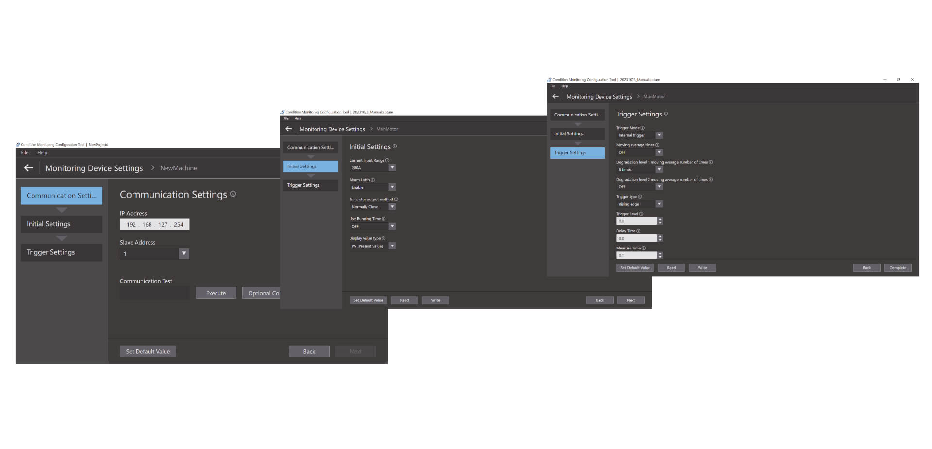
Configurare ușoară în trei pași
Unealta de configurare pentru monitorizarea condiției permite configurarea în loturi a unor game largi de dispozitive de monitorizare, cum ar fi a celor care monitorizează motoare, temperaturi, izolații și radiatoare. Poate fi folosită fără abilități speciale, ceea ce reduce efortul de instruire. Configurarea poate fi realizată în numai trei pași: configurarea comunicării, configurarea inițială și configurarea declanșatorilor. * 1 Prin operabilitatea de înalt nivel, unealta crește și productivitatea la fața locului.
Videoclipuri

-
K6CM Motor Condition Monitoring Device
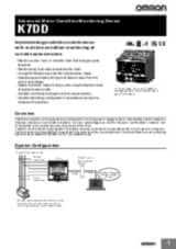
K6CM takes the burden of monitoring motors off maintenance engineers. Motors can be maintained in advance of failure due to deterioration. K6CM (comprehensive current diagnosis type) can consistently monitor motor conditions by observing the current waveform of the motor. Additionally, you can understand the motor's maintenance timing without depending on an engineer, because K6CM provides threshold value setting.
02:40
K6CM Motor Condition Monitoring Device
K6CM takes the burden of monitoring motors off maintenance engineers. Motors can be maintained in advance of failure due to deterioration. K6CM (comprehensive current diagnosis type) can consistently monitor motor conditions by observing the current waveform of the motor. Additionally, you can understand the motor's maintenance timing without depending on an engineer, because K6CM provides threshold value setting.
-

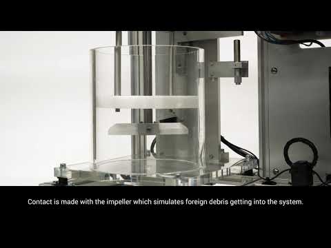
K6CM Demo Video
05:48
K6CM Demo Video


OMRON K6CM Conveyor Chain Demonstration Video


OMRON K6CM Misaligned Drive Belts Demonstration Video

OMRON K6CM Mixer Demonstration Video


OMRON K6CM Pump Cavitation Demonstration Video


OMRON K6CM Spray Dryer Demonstration Video
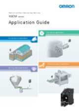
Soluţii
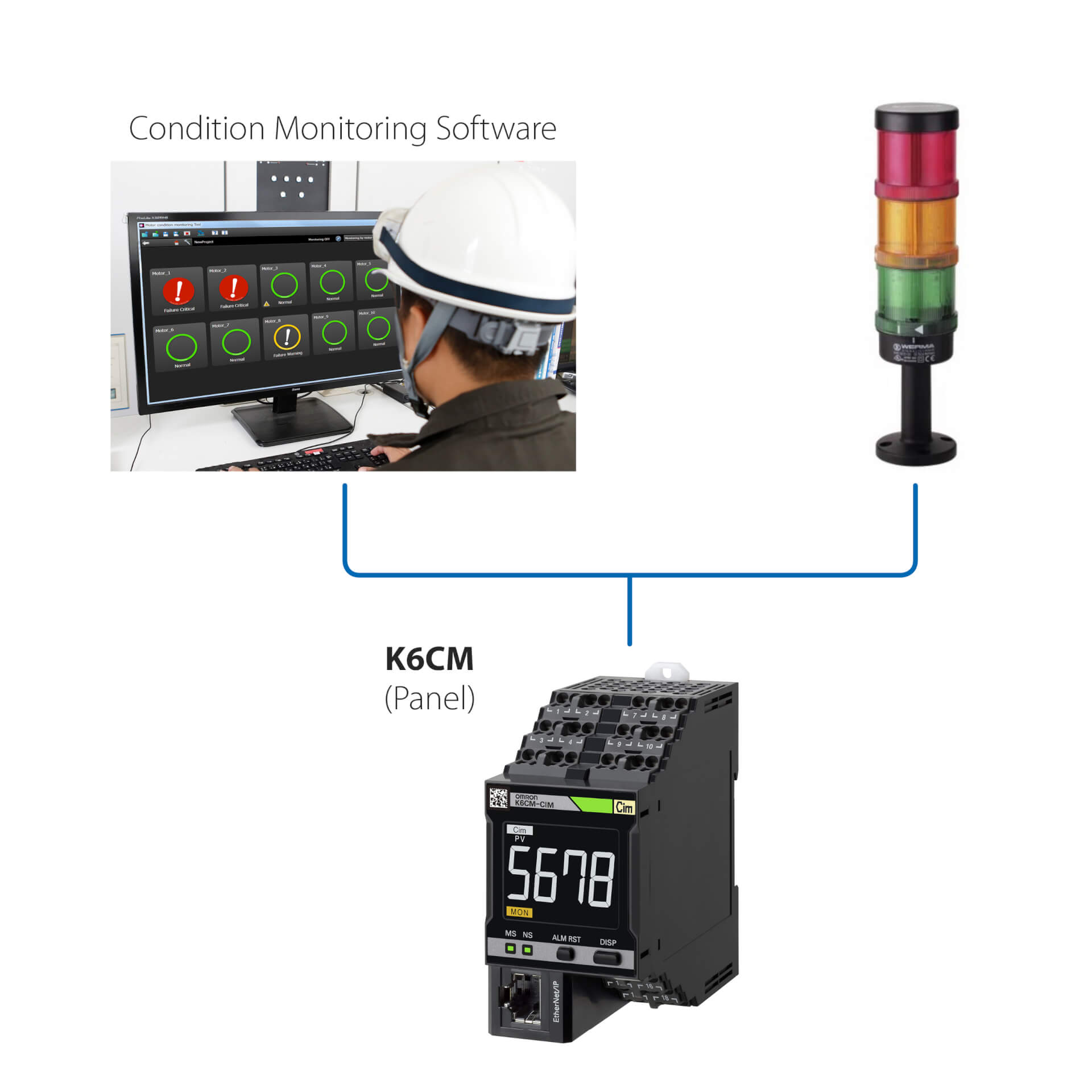
Instalare autonomă (fără PLC)
Această soluţie simplă permite:
- Monitorizarea stării motorului prin LED-ul integrat sau software-ul de monitorizare a stării
- Configurarea controlerelor prin software-ul de monitorizare a stării furnizat cu dispozitivul
- Interfaţarea K6CM cu orice dispozitiv I/O extern (ieşire digitală)
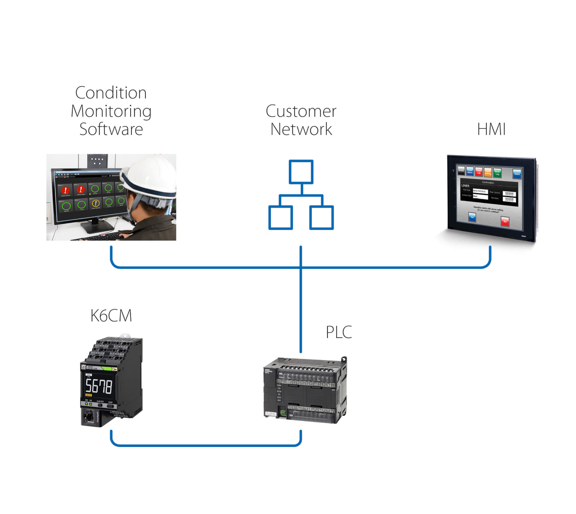
Instalare autonomă (cu PLC)
Pe lângă acţiunile permise de soluţia precedentă, această soluţie asigură:
- Monitorizarea stării motorului prin software-ul de monitorizare a stării, care rulează pe un PC conectat prin intermediul unui PLC
- Declanşarea, prin intermediul PLC, a unor acţiuni în urma avertismentelor/alarmelor detectate de K6CM
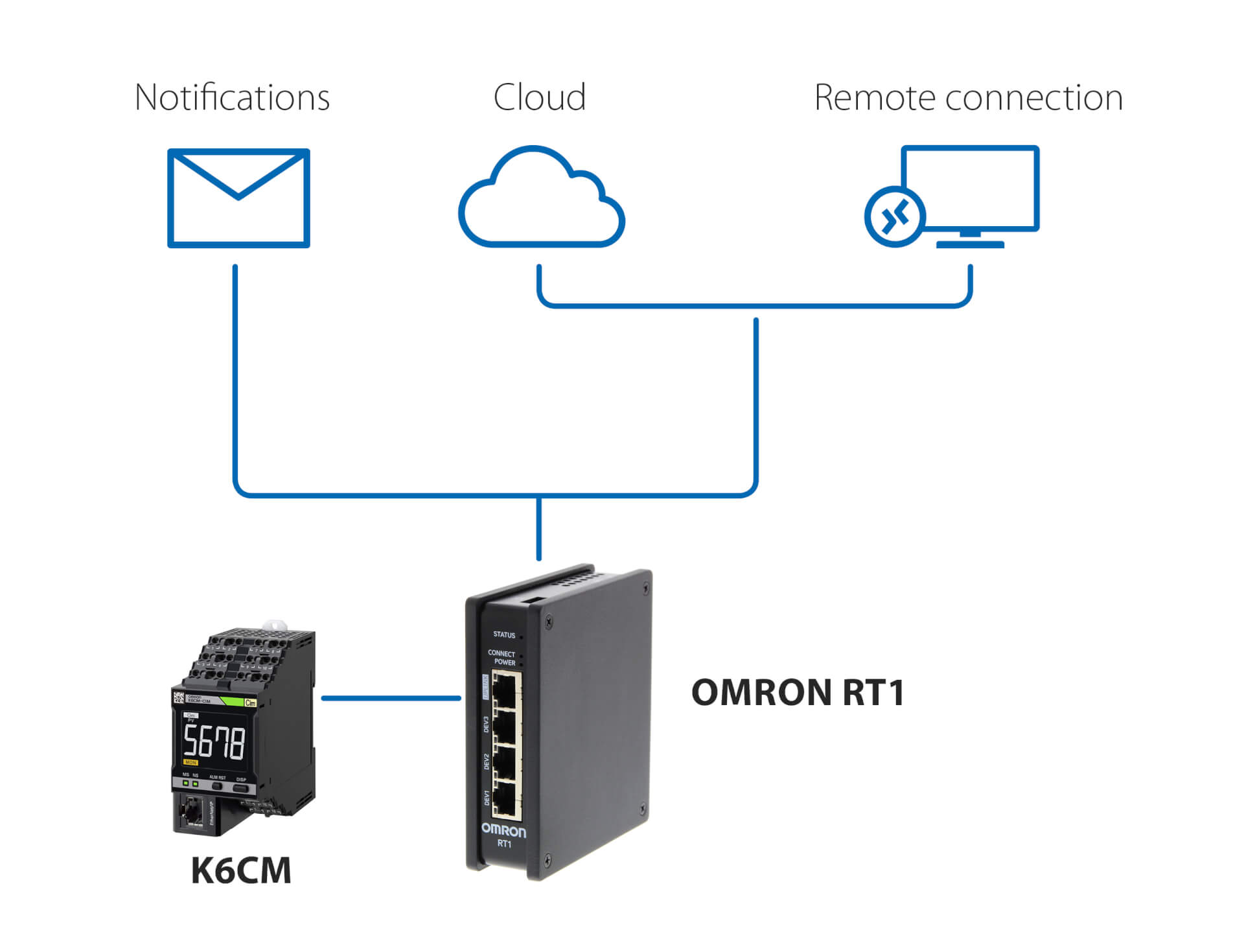
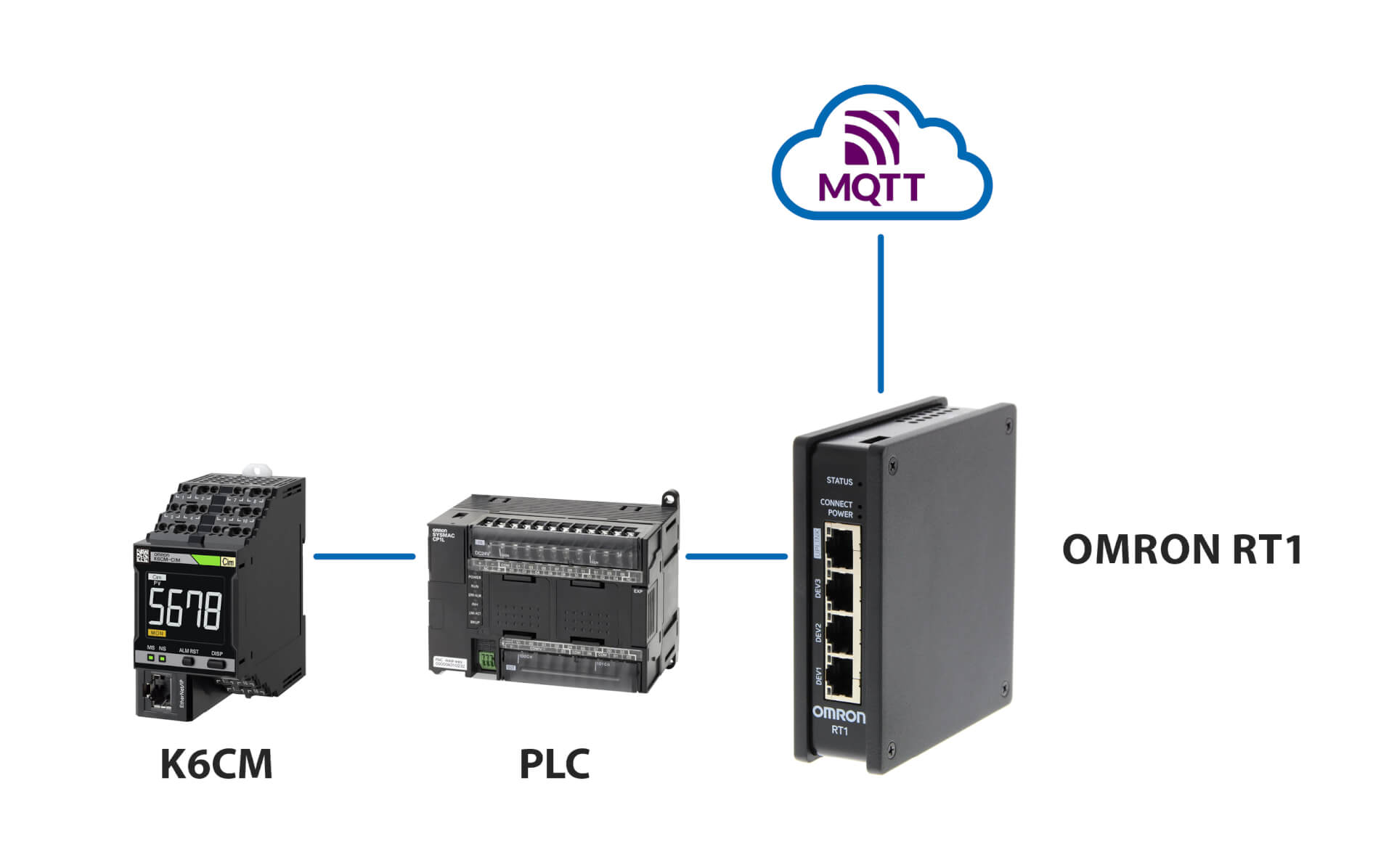
Notificări şi monitorizare la distanţă – fără PLC
Această soluţie, care utilizează OMRON RT1 ca gateway, permite:
- notificări prin e-mail/SMS în cazul detectării unor anomalii de către K6CM
- conectare sigură (gestionată de RT1) la cloud printr-o conexiune LAN sau 4G
- conexiune sigură pentru monitorizarea şi configurarea de la distanţă a K6CM, folosind software-ul de monitorizare a stării furnizat cu controlerul
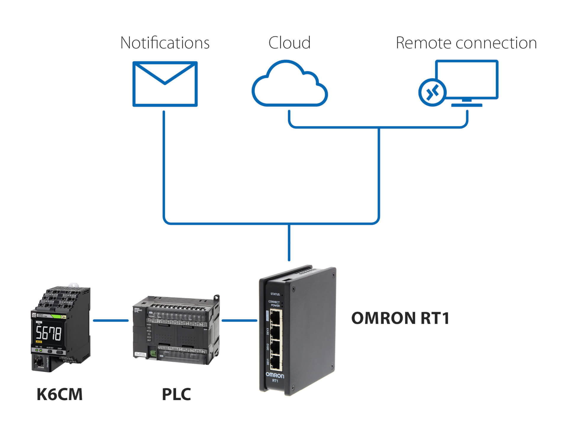
Notificări şi monitorizare la distanţă – cu PLC
Această soluţie, care utilizează orice PLC şi OMRON RT1 ca gateway, permite:
- notificări prin e-mail/SMS în cazul detectării unor anomalii de către K6CM
- conectare sigură (gestionată de RT1) la cloud printr-o conexiune LAN sau 4G
- conexiune sigură pentru monitorizarea şi configurarea de la distanţă a K6CM, folosind software-ul de monitorizare a stării furnizat cu controlerul
Conexiunea la serverul MQTT
Produse conexe
-
Dispozitiv de monitorizare a stării motorului – monitorizarea izolaţiei
-
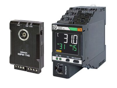
Dispozitiv de monitorizare a stării motorului – monitorizarea vibraţiilor
-
Monitorizarea stării pe bază de termografie
-
Dispozitiv de monitorizare a stării – monitorizarea izolaţiei
Documentare